| Legal Information |
|

 |
In a series RLC circuit there is a frequency at which the inductive reactance of the inductor becomes equal in value to the capacitive reactance of the capacitor. |
Series Resonance circuits are one of the most important circuits used electrical and electronic circuits. They can be found in various forms such as in AC mains filters, noise filters and also in radio and television tuning circuits producing a very selective tuning circuit for the receiving of the different frequency channels.
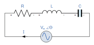
Consider the simple series RLC circuit shown above. Total circuit impedance is
Z = R + jX
Resonance occurs when ZL = ZC, that is
ωL =1 ωCwhere ω = 2πf , so 2πfL =1 2πfCor 4π2f2 =1 LCand fr =1 2π √LC
So the total impedance of the series circuit becomes just the value of the resistance and therefore: Z = R. At resonance the impedance of the series circuit is at its minimum value and equal only to the resistance, R of the circuit.
At frequencies above ft, because inductive reactance ZL > ZC, there is a positive phase shift. Similarly, when frequencies are below ft, becase ZC >ZL , there is a negative phase shift
If the series RLC circuit is driven by a variable frequency at a constant voltage, then the magnitude of the current, I is proportional to the impedance, Z, therefore at resonance the power absorbed by the circuit must be at its maximum value as P = I2Z.
If the frequency is now reduced or increased until the average power absorbed by the resistor in the series resonance circuit is half that of its maximum value at resonance, two frequency points are produced called the half-power points which are -3dB down from maximum, taking 0dB as the maximum current reference.
These -3dB points give a current value that is 70.7% of its maximum resonant value which is defined as: 0.5( I2 R ) = (0.707 x I)2 R.
The point corresponding to the lower frequency at half the power is called the "lower cut-off frequency", fL and the point corresponding to the upper frequency at half power being called the "upper cut-off frequency", fH.
The distance between these two points, i.e. ( fH - fL ) is the Bandwidth, (BW) and is the range of frequencies over which at least half of the maximum power and current is provided.
| Search Knowledge Base | Feedback |