
| Legal Information |
|

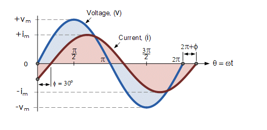 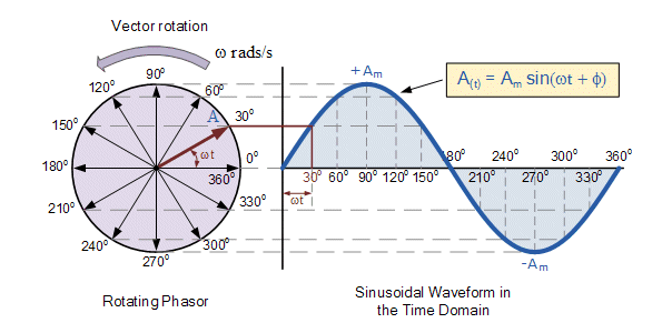  | A phasor, a combination of the two words phase and vector, is a mathematical means of representing a sinusoidal function with amplitude A, angular frequency (ω), and initial phase (Φ) as are time-invariant. This representation also includes a graphical representation in the form of a phasor diagram, shown left. The vector representation is described by a complex number of the form a + bj, where j is a complex (or imaginary) number equal to √-1, an impossible number hence imaginary.
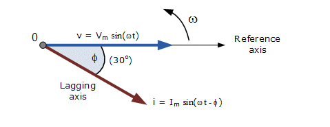
The top figure showing two sine waves with the current wave (red) lagging the voltage (blue) by Φ in this case 30o. These two sinusoidal quantities will be written as: Vt = Vm * sin(ωt) and A sine wave can be represented as a rotating wheel with phase shifted sine waves lagging or leading in the rotation cycle. Each wave being described mathematically by a complex number of the form a + bj, where j is a complex (or imaginary) number equal to √-1, an impossible number hence imaginary. |
| It is common in electrical networks to have multiple sinusoids all with the same frequency, but different amplitudes and phases. The circuit right shows the three main passive components, components incapable of controlling current by means of another electrical signal, of resistors, capacitors and inductors . The circuit is a RLC one, named after the symbols used to define resistors ®, capacitors © and inductors (L) Since the inductive and capacitive reactance's XL and XC are a function of the supply frequency, the sinusoidal response of a series RLC circuit will therefore vary with frequency, ƒ. | 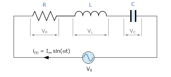 |
The individual voltage drops across each circuit element of R, L and C element will be "out-of-phase" with each other as defined by:
i(t) = Imax sin(ωt)
The amplitude of the source voltage across all three components in a series RLC circuit is made up of the three individual component voltages, VR, VL and VC with the current common to all three components.
|
The vector diagrams will therefore have the current vector as their reference with the three voltage vectors being plotted with respect to this reference. The phasor diagram for a series RLC circuit is produced by combining together the three individual phasors and adding these voltages vectorially. The resulting vector VS is obtained by adding together two of the vectors, VL and VC and then adding this sum to the remaining vector VR. The resulting angle obtained between VS and i will be the circuits phase angle as shown below. | 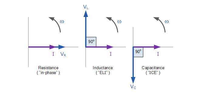 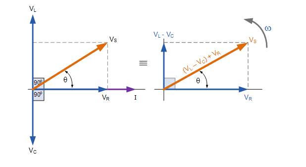
|
Kirchhoff's voltage law ( KVL ) for both loop and nodal circuits states that around any closed loop the sum of voltage drops around the loop equals the sum of the EMF's. Then applying this law to the these three voltages will give us the amplitude of the source voltage, VS as.
VS = VR + VL + VCWhere
VS = R * I + ωL * I +I ωC
| Search Knowledge Base | Feedback |