| Legal Information |
|

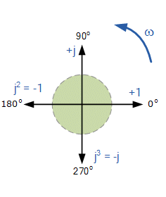
The general term for the impedance (Z) of a component is Z = R + jXFor a resistor this becomes Z = R The impedance of a capacitor is ZC =where ω is the angular frequency (given by ω = 2πf, where f is the frequency of the signal), and C is the capacitance of the capacitor. | This represents the following phase vector (phasor) diagram, where a component in an AC circuit is represented as a vector having a real (resistive) value and an imaginary (reactive) value
|
| As the j-operator is being used to indicate the counter-clockwise rotation of a vector, each successive rotation of " j ", j2, j3 etc, will force the vector to rotate through a fixed angle of 90o in a counter-clockwise direction as shown in the figure left. Likewise, if the multiplication of the vector results in a -j operator then the phase shift will be -90o, i.e. a clockwise rotation. 90o rotation = j = √-1 |

|
A = x +jy and B = w + jz, then
A + B = (x + w) + j * (y + jz), and
A - B = (x - w) + j * (y - jz)
The multiplication of complex numbers follows more or less the same rules as for normal algebra along with some additional rules for the successive multiplication of the j-operator where: j2 = -1. S,
A * B = (x + jy) * (w + jz) = xw + jzx + jyw + j2yz = xw + j * (zx + yw) - yz = xw - yz + j * (zx + yw)
The division of complex numbers is a little more difficult to perform. The denominator is considered to be one half of the quadratic equation a2 - b2 =0. This resolves to (a + b) * (a - b) = 0. If b is an imaginary number then b2 will be a real number. So multiplying the denominator by its conjugate pair, a process termed rationalising" will make the calculation possible. Let
Multiplying top and bottom by the conjugate of the denominatot, 2 - j3, givesA B=4 + j1 2 + j3
A B=(4 + j1) * ( 2 - j3) (2 + j3) * ( 2 - j3)=8 - j12 + j2 - j23 4 -j6 + j6 - j29=8 + 3 - j10 4 + 9=11 - j10 13
The voltage of an inductor leads the current by 90 degrees. The following equation is used for the impedance of an inductor:
ZL = jωLwhere ZL is the impedance of the given inductor, ω is the angular frequency, and L is the inductance of the inductor. The conclusions that can be drawn from this formula: are
| Search Knowledge Base | Feedback |