| Legal Information |
|

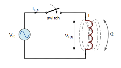
 | Inductors and chokes are essentially coils or loops of wire that are either wound around a hollow tube former (air cored) or wound around some ferromagnetic material (iron cored) to increase their inductive value called inductance.
Inductors store energy in the form of a magnetic field that is created when a voltage is applied across the terminals of an inductor. The growth of the current flowing through the inductor is not instant but is determined by the component's self-induced back emf value. Then for an inductor coil, this back emf voltage VL is proportional to the rate of change of the current flowing through it. The flow of AC current through an inductor behaves very differently to that of a steady state DC voltage. With an AC circuit, the opposition to the current flowing through the coils windings not only depends upon the inductance of the coil but also the frequency of the applied voltage waveform as it varies from its positive to negative values. |
The actual opposition to the current flowing through a coil in an AC circuit is determined by the reactance of the coil, which is represented by a complex number.
As with resistance, reactance is measured in Ohm's but is given the symbol "Z" to distinguish it from a purely resistive "R" value and as the component in question is an inductor, the reactance of an inductor is called Inductive Reactance, ( ZL) and is measured in Ohms.
ZL = 2πfL --- (1)Where f is the frequency in Hertz and L is the inductance of the coil in Henries.. This is normally defined as ωL , where ω equals 2πf.
 | The back emf arises due to the lines of electro-magnetic force (Φ) generated by a current inducting a voltage.that opposes the flow of the current. The size of the back emf is proportional to the rate of change of current. For an AC current that will be
d(sin ωt)
dt
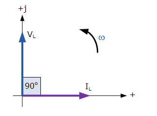
=k * cos ωt, where k is a constant - essentially the inductance of the coilThis phase relationship between the voltage and current flowing through a pure inductor circuit is often referred to as "ELI" (pronounced Ellie as in the girls name). ELI stands for Electromotive force first in an AC inductance, L before the current I. |
From equation (1) above, it can be seen that the inductive reactance of an inductor increases as the frequency increases therefore inductive reactance is proportional to frequency. So, as the frequency increases the impedance increases and the current increases. Re-stating Ohm's law this gives
Current, I =And re-stating the back emf equation above to allow for phase differencesVoltage Opposition to current flow=V ZL
IL(t) = Imax * sin ωt and VL(t) = L *then the voltage across an AC inductance will be defined as:d(sin ωt + Θ) dt= ω * L * Imax * cos (ωt + Θ)
VL(t) = ω * L * Imax * sin (ωt + 90o)
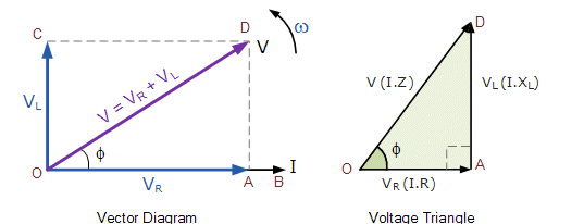
 | The voltage and current in a resistive circuit are both in phase. The current lags the voltage in an AC inductance (pure) circuit therefore the inductance voltage will be 90o in front of the resistive voltage. From the vector diagram right, the line OB is the horizontal current reference and line OA is the voltage across the resistive component, which is in-phase with the current. Line OC shows the inductive voltage, which is 90o in front of the current therefore it can still be seen that the current lags the purely inductive voltage by 90o. Line OD gives us the resulting supply voltage. |
Then:
As the current lags the voltage in a pure inductance by exactly 90o the resultant phasor diagram drawn from the individual voltage drops VR and VL represents a right angled voltage triangle shown above as OAD.
Since VR = I * R and VL = I * XL the applied voltage will be the vector sum of the two as follows:
V2 = VR2 + VL2re-arranging gives
V = √VR2 + VL2
V = √(I * R)2 + ( I * XL)2
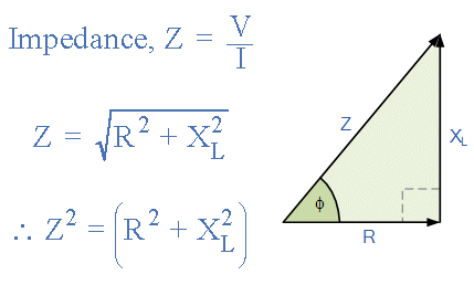
I =√R2 + XL2 is the circuit's impedance.V √R2 + XL2
 | Impedance, Z is the overall opposition to current flowing in an AC circuit that contains both Resistance, ( the real part ) and Reactance ( the imaginary part ). Impedance is also measured in units of Ohms, Ω The figure left represnts the resistance, reactance and impedance of the circuit. This means that the positive phase angle, Θ between the voltage and current is given as. sin Θ = |
| Search Knowledge Base | Feedback |